Flow Measurement
| Home | | Pharmaceutical Technology |Chapter: Pharmaceutical Engineering: Fluid Flow
The Bernoulli theorem can also be applied to the measurement of flow rate. Consider the passage of an incompressible fluid through the constriction.
FLOW MEASUREMENT
The
Bernoulli theorem can also be applied to the measurement of flow rate. Consider
the passage of an incompressible fluid through the constriction shown in Figure
2.6. The increase in kinetic energy as the velocity increases from u1
to u2 is derived from the pressure energy of the fluid, the pressure
of which drops from P1 to P2, the latter being recorded
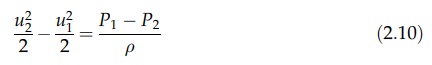
by manometers. There is no change in height, and equation (2.5) can be
rearranged to give
The
volumetric flow rate Q =
u1a1 =
u2a2. Therefore, by rearrangement,
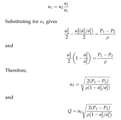
This
derivation neglects the correction of kinetic energy loss due to non-uniformity
of flow in both cross sections and the frictional degradation of energy during
passage through the constriction. This is corrected by the introduction of a
numerical coefficient, CD, known as the coefficient of discharge.
Therefore,
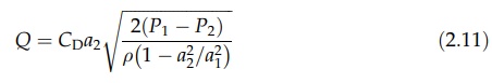
The
value of CD depends on conditions of flow and the shape of the
constriction. For a well-shaped constriction (notably circular cross section),
it would vary between 0.95 and 0.99 for turbulent flow. The value is much lower
in laminar flow because the kinetic energy correction is larger. The return of
the fluid to the original velocity by means of a diverging section forms a
flow-measuring device known as a Venturi meter.
The
Venturi meter is shown in Figure 2.7A. The converging cone leads to the
narrowest cross section, known as the throat. The change in pressure is
measured across this part of the meter and the volumetric flow rate is found by
substitution into equation (2.11). Values of the coefficient of discharge are
given in the preceding paragraph. The diverging section or diffuser is designed
to induce a gradual return to the original velocity. This minimizes eddy
formation in the diffuser and permits the recovery of a large proportion of the
increased kinetic energy as pressure energy. The permanent loss of head due to
friction in both converging and diverging sections is small. The meter is
therefore efficient.
When
the minimization of energy degradation is less important, the gradual, economic
return to the original velocity may be abandoned, compen-sation for loss of
efficiency being found in a device that is simpler, cheaper, and more adaptable
than the Venturi meter. The orifice meter, to which this state-ment applies,
consists simply of a plate with an orifice. A representation of flow through the
meter is depicted in Figure 2.7B, indicating convergence of the fluid stream
after passage through the orifice to give a cross section of minimum area
called the vena contracta. The downstream pressure tapping is made at this
cross
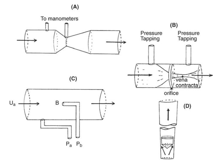
FIGURE 2.7 Flow meters: (A) Venturi meter,
(B) orifice meter, (C) Pitot tube, and (D) rotameter.
The volumetric flow rate would be given by equation (2.6) for which a2
is the jet area at the vena contracta.
The measurement of this dimension is inconvenient. It is therefore related to
the area of the orifice, a0,
which can be accurately measured by the coefficient of contraction, Cc,
defined by the relation
Cc = a2/a0
The
coefficient of contraction, frictional losses between the tapping points, and
kinetic energy corrections are absorbed in the coefficient of discharge. The
volumetric flow rate is then
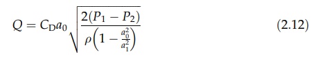
The
term [1 - (a02/a12)] approaches
unity if the orifice is small compared to the pipe cross section. Since P1
- P2 = Δhρg, Δh being the
difference in head developed by the orifice, equation (2.12) reduces to
Q
= CD a0 (2Δhg)1/2 (2:13)
The
value of CD for the orifice meter is about 0.6, varying with
construction, the ratio a0/a1, and flow conditions
within the meter. Because of its complexity, it cannot be calculated. After
passage through the orifice, flow disturbance during retardation causes the
dissipation of most of the excess kinetic energy as heat. The permanent loss of
heat is therefore high, increasing as the ratio of a0/a1
falls, ultimately reaching the differential head produced within the meter.
When constructional requirements and methods of installation are followed, the
cor-recting coefficients can be derived from charts. Alternatively, the meters
can be calibrated.
The
Bernoulli theorem may be used to determine the change in pressure caused by
retardation of fluid at the upstream side of a body immersed in a fluid stream.
This principle is applied in the Pitot tube, shown in Figure 2.7C. The fluid
velocity is reduced from ua, the velocity of the fluid filament in
alignment with the tube, to zero at B, a position known as the stagnation
point. The pressure, Pb, is measured at this point by the method
shown in Figure 2.7C. The undisturbed pressure, Pa, is measured in
this example with a tapping point in the wall connected to a manometer. Since
the velocity at B is zero, equation (2.10) reduces to
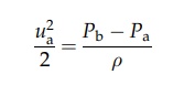
and
ua can be calculated. Since only a local velocity is measured,
variation of velocity in a section can be studied by altering the position of
the tube. This procedure must be used if the flow rate in a pipe is to be
measured. The mean velocity is derived from velocities measured at different
distances from the wall. This derivation and the low pressure differential
developed render the Pitot tube less accurate than either the Venturi tube or
the orifice meter for flow measure-ment. However, the tube is small in
comparison with the pipe diameter and therefore produces no appreciable loss of
head.
The
rotameter (a variable area meter),
shown in Figure 2.7D, is commonly used, giving a direct flow rate reading by
the position of a small float in a vertical, calibrated glass tube through
which the fluid is flowing. The tube is internally tapered toward the lower end
so that the annulus between float and wall varies with the position of the
float. Acceleration of the fluid through the annulus produces a pressure
differential across the position of the float and an upward force on it. At the
equilibrium position, which may be stabilized by a slow rotation of the float,
this upward force is balanced by the weight force acting on the float. If the
equilibrium is disturbed by increasing the flow rate, the balance of weight
force and the pressure differential are produced by movement of the float
upward to a position at which the area of the annulus is bigger. For accurate
measurement, the rotameter is calibrated with the fluid to be metered. Its use
is, however, restricted to that fluid.
Related Topics