What are d-block metals?
| Home | | Inorganic Pharmaceutical Chemistry |Chapter: Essentials of Inorganic Chemistry : Transition Metals and d-Block Meta Chemistry
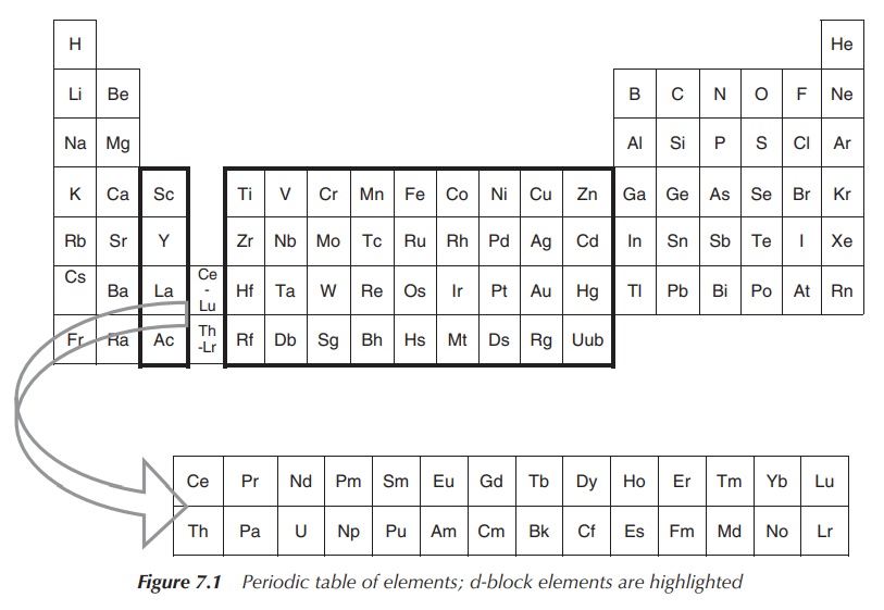
The elements in groups 3–12 as shown in the schematic periodic table below are defined as the so-called d-block metals. The term transition metal is also often used to describe this group of elements.
What
are d-block metals?
The elements in groups 3–12 as shown in the schematic periodic
table below are defined as the so-called d-block metals. The term transition metal is also often used to
describe this group of elements. However, the IUPAC (International Union of
Pure and Applied Chemistry) defines transition metals as elements with an
incomplete d subshell or elements that can form a cation with an incomplete d
subshell. Therefore, the group 12 metals zinc (Zn), cadmium (Cd) and mercury
(Hg) are not typically classified as transition metals (Figure 7.1) .
Elements in the f-block, the so-called lanthanides and
actinides, have been in the past called inner
transition metals. Nowadays, they
are more often referred to as f-block
elements and selected examples will be discussed in Chapter 11.
Each group of d-block metals is formed by three members and is
therefore called a triad. Sometimes,
elements are grouped according to their chemical behaviour. One example is the
group of platinum group metals, which encompasses ruthenium (Ru), osmium (Os),
palladium (Pd) and platinum (Pt). Sometimes, you can find the term heavier d-block metals, which refers to
d-block metals of the second and third row.
Electronic configurations
Generally, the ground-state electronic configurations of the
first, second and third-row d-block metals follows the progressive filling of
the 3d, 4d and 5d atomic orbitals, respectively. Nevertheless, there are exceptions,
such as the ground state of chromium, which is [Ar]4s13d5
rather than [Ar]4s23d4. The reasons are fairly
complicated and will not be further discussed in this book (Table 7.1).
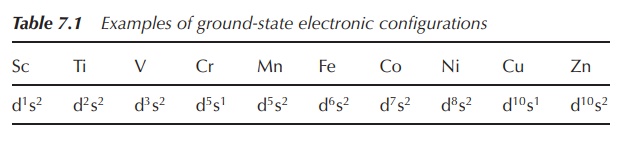
d-Block metals can show several oxidation states as their valence electrons can be present in more than one atomic orbital. M2+ and M3+ ions of the first-row d-block metals follow the general formula [Ar]3dn. The electronic configurations for second- and third-row d-block metals are again more complicated and will not be further discussed in this book.
Characteristic properties
Nearly all d-block metals are hard, malleable and ductile, and
conduct electricity and heat. Most of them will form one of the typical metal
structures. Exceptions are manganese (Mn), Zn, Cd and Hg. Only three d-block
elements, namely iron (Fe), cobalt (Co) and nickel (Ni), are known to produce a
magnetic field.
d-Block metals tend to readily form complexes
with a characteristic colour if their ground-state electronic configuration is
different from d0 or d10. Complex formation is often
characterised by a colour change. For example, [CoF6]3−
is green, whereas [Co(NH3)H2O]3+ is red and
[Co(H2O)6]3+ is blue.
Coordination complexes are defined as chemical structures that
consist of a central atom or metal ion, and
the surrounding molecules or anions called the ligands.
Paramagnetism is a phenomenon that is often
observed for d-block metal compounds. This is a result of the presence of
unpaired electrons and can be investigated using electron paramagnetic
resonance (EPR) spectroscopy. As a result, abnormalities in the NMR spectra can
be observed such as broadening of the signals or unusual chemical shifts.
Paramagnetism is defined as the phenomenon whereby some
materials show magnetic properties only once
they are exposed to a magnetic field. Outside this magnetic field, no magnetic
properties are seen. This is in contrast to ferromagnets, which show magnetic
properties independent of the environment.
Coordination numbers and geometries
d-Block metal compounds readily form complexes displaying
different coordination numbers and geome-tries. In this section, we will
restrict our discussion to complexes with only one metal centre (mononuclear
complex). Also, it is important to note that the discussed geometries are
regular geometries, which in practice can often be distorted as a result of
steric hindrances. Additionally, in reality, fluxional behaviour in solution
can be observed if the energy difference between the different structures is
small enough, but we will restrict the following discussion to the solid state
of complexes.
In general, steric and electronic factors dictate the
coordination number. Sterically demanding ligands are more likely to form
complexes with a low coordination number. In contrast, complexes containing
small ligands and a large metal centre favour high coordination numbers (Figure
7.2).
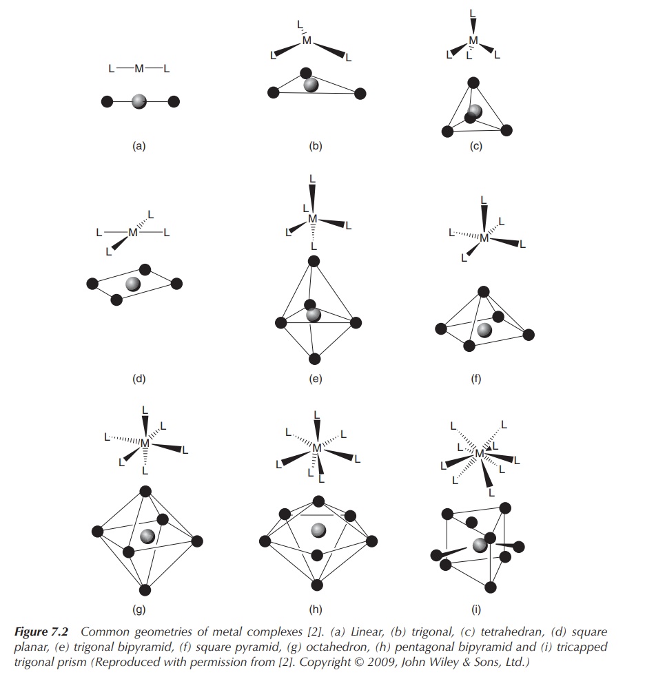
Figure 7.2 Common geometries of metal complexes . (a) Linear, (b) trigonal, (c) tetrahedran, (d) square planar, (e) trigonal bipyramid, (f) square pyramid, (g) octahedron, (h) pentagonal bipyramid and (i) tricapped trigonal prism (Reproduced with permission from . Copyright © 2009, John Wiley & Sons, Ltd.)
The Kepert
model is typically used to describe the shape of d-block metal complexes.
The metal is defined to be the centre of the complex, and the ligands are
arranged freely on a sphere around the centre. Only ligands are taken into
consideration when determining the geometry of the complex. This is in contrast
to the valence shell electron pair repulsion (VSEPR) model, which is used to
determine the structure of p-block element compounds, where also nonbonding
electrons are considered.
The η-nomenclature for ligands is used in organometallic chemistry and
describes the number of atoms in a
ligand that directly interact with the metal. The prefix η (eta) is accompanied by a number, which
equals the number of atoms coordinating to the metal. This is called hapticity of a ligand.
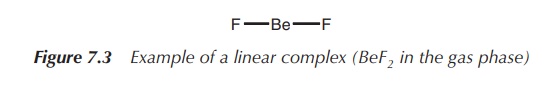
1. Coordination number 2: linear
A coordination number of 2 can be typically found for the metals
Cu(I),1 Ag(I), Au(I) and Hg(II). The metal forms the centre of the
complex, and the two ligands are arranged at 180∘ to each other (Figure
7.3).
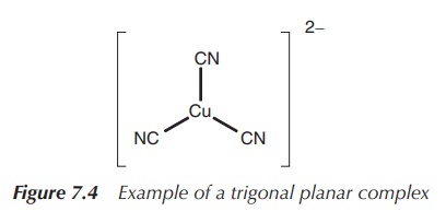
2. Coordination number 3: trigonal planar or trigonal pyramidal (less common arrangement)
In general, trifold coordination of a metal centre is not very
common. There are examples of metals with a full d-orbital (d10
metals), which form trigonal planar structures. This means three ligands are
arranged around the metal centre in one plane with 120∘ angle to each other.
Examples include complexes of Cu(I), for example, in [Cu(CN)3]2−
and Ag(I), Au(I), Hg(II) and Pt(0) in [Pt(PPh3)3] (Figure
7.4).
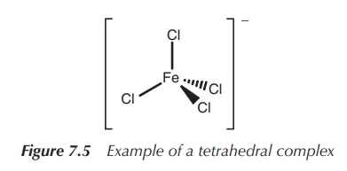
3. Coordination number 4: tetrahedral or square planar
The coordination number 4 is extremely common for d-block metal
complexes. Most frequently, a tetrahedral arrangement can be observed. Examples
include [MnO4]2−, [FeCl4]− and [CrO4]2−
(Figure 7.5).
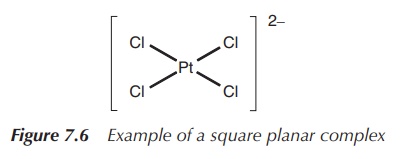
The square planar arrangement in which all four ligands are arranged around the metal centre in one plane is less commonly observed and often connected to d8 metals. Nevertheless, some of these complexes are very important as a result of their medical application. For example, the square planar complex [PtCl4]2− is commonly used as a precursor to the known chemotherapeutic agent cisplatin, whereas square planar complexes [PdCl4]2−, [AuCl4]− and [RhCl(PPh3)3] are all under investigation for their use in medicine (Figure 7.6).
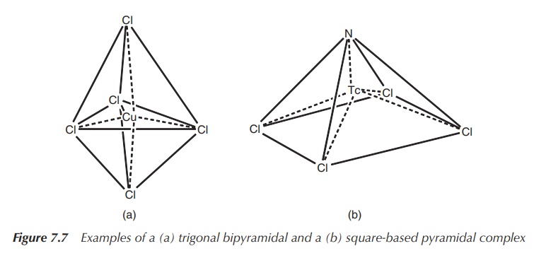
4. Coordination number 5: trigonal bipyramidal or square-based pyramidal
The energy difference between the trigonal bipyramidal structure
and the square-based pyramidal structure is usually fairly small and therefore
many structures lie in reality between those two. Examples for simple trigonal
bipyramidal structures include [CdCl5]3− and [CuCl5]3−,
whereas [WCl(O)]− and [TcCl4(N)]− form
square-based pyramidal structures typical for a series of oxo and nitrido
complexes (Figure 7.7).
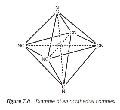
5. Coordination number 6: octahedral or trigonal prismatic (less common geometry)
Octahedral geometry is most commonly observed for the
coordination number 6. Metals of all kinds of elec-tronic configurations form
octahedral complexes, for example, [Mn(OH2)6]3+,
[V(OH2)6]3+, [Fe(CN)6]3−
and [Fe(OH2)6]2+ (Figure 7.8).
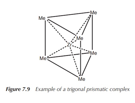
It was long believed the octahedral geometry
is the only geometry for coordination number 6 in existence, but eventually
examples of trigonal prismatic coordination have been confirmed by X-ray
analysis. Examples are [ZrMe6]2− and [ReMe6]
(Figure 7.9).
6. Coordination number 7 and higher
Coordination numbers of 7 and higher are most commonly observed
for d-block metals of the second and third row. Geometries can become fairly
complicated and are not further discussed here.
Crystal field theory
Many transition-metal complexes are coloured.
This and other spectroscopic properties, such as magnetism and hydration
enthalpies, can be explained with the so-called crystal field theory (CFT).
The
CFT describes the degeneration of the d- and f-orbitals in transition-metal
complexes. It does not attempt to describe any type of chemical bonds.
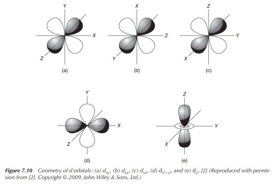
CFT is based on the interaction of a
positively charged cation and the nonbinding (negatively charged) electrons of
the ligand. The general principle is that the five d orbitals are degenerated,
meaning that they do not occupy the same energy level anymore. Once the ligands
approach the central positively charged cation, the electrons of the ligands
will become closer to some of the d orbitals of the metal. This results in the
degeneration of the d orbitals. Electrons in d orbitals that are closer to the
ligands will occupy a higher energy level as the negatively charged electrons
will repel each other (Figure 7.10).
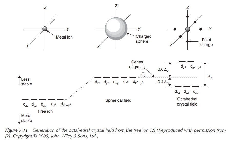
The most common type of transition-metal complexes is octahedral
complexes, where the central metal is coordinated by six ligands. The five d
orbitals are split into two sets with the same energy level, the energy
difference is called Δoct. The orbitals dxy, dxz
and dyz occupy the lower
energy level as they are further away from the ligands. Ligands can be seen as
approaching the central metal along the axes, where the orbitals dxy, dxz and dyz,
referred to as t2g, are located in between the axes. In contrast,
the two remaining d orbitals dx2−y2 and dz2 , referred to
as eg, are positioned along the axes (from where the ligands
approach) and there-fore occupy a higher energy level within an octahedral
complex.
Figure 7.11 shows how energy levels of d orbitals change,
ranging from the energy of d orbitals of the free metal ion, followed by the
energy of d orbitals of the complex in a spherical field and the split energy
levels observed in an octahedral field.
There are several factors influencing this splitting of the d
orbitals:
•
The metal ion itself.
•
The oxidation state of the metal ion: The energy difference increases with increasing oxidation state for
any given metal.
•
The nature of the ligand: Some ligands encourage a large value for , whilst the
formation of complexes with other ligands results in a small splitting of t2g
and eg orbital sets. The spectrochemical series is a list that shows ligands in
the order in which they produce a splitting, ranging from small to large Δ:
I− < Br−
< S2−
< SCN−
< Cl−
< NO3−
< N3−
< F−
< OH−
< C2O42−
< NH3
< NO2−
< PPh3 < CN− < CO
•
The geometry of the transition-metal complex: The arrangement of energy level
changes and is dependent on the geometry of the complex.
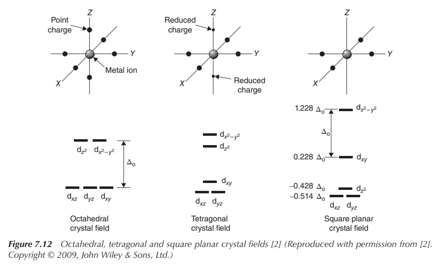
Figure 7.11 shows the energy diagram for octahedral complexes.
In Figure 7.12, the CFT splitting diagrams for other geometries, including
tetrahedral, square planar and trigonal bipyramidal complexes are shown.
It is interesting to observe what happens when these orbitals
are filled with electrons. The lowest energy levels will be filled first, and
Hund’s rule states that orbitals are filled with one electron first, before the
elec-trons are paired. The Pauli
Exclusion Principle states that two electrons in the same orbital are not
allowed to have the same spin; nevertheless, it consumes energy to change the
spin of an electron. Looking at octahedral complexes and the energy scheme
shown in Figure 7.11, filling the orbitals with one, two or three electrons is
straightforward. Each of the t2g orbitals will be filled with one
electron. The addition of the next electron leads now to two possibilities.
Electron number 4 can either be added to a vacant eg orbital, which
means the energy ΔOct is needed to promote it to this level. These
types of complexes are called high-spin
complexes. Alternatively, the fourth electron can be added to one of the
already occupied orbitals of t2g once the electron spin has changed.
These complexes are called as low-spin
complexes. Depending on the size of ΔOct, different types of
complex are formed. If ΔOct is very large, it consumes less energy
to fill a t2g orbital with a second electron; vice versa, if ΔOct
is relatively small, it is energetically favourable to promote the fourth
electron to the eg level.
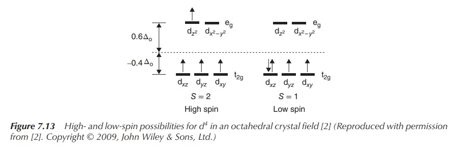
Examples of a low- and high-spin complex with four electrons in
the d orbitals are shown in Figure 7.13. Both complexes have the same metal ion
in the same oxidation state as the centre, and ΔOct depends only on
the ligands. The same discussion follows for the addition of a fifth electron.
As mentioned at the beginning of this chapter, CFT can be used to explain the colour of these often brightly coloured transition metals. When a molecule absorbs a photon, one or more electrons are temporarily pro-moted within the set of split d orbitals from the lower to the higher energy level. This leads to a complex in an excited state, and the energy difference to the ground state equals the energy of the absorbed photon. The latter energy is inversely related to the wavelength of the light absorbed. Therefore the transition-metal complex can be seen in the complementary colour.