Grinding Equipment
| Home | | Pharmaceutical Technology |Chapter: Pharmaceutical Engineering: Size, Reduction and Classification
The following equipment is in regular use for dry grinding pharmaceutical materials: edge and end runner mills, hammer mill, pin mill, and ball mill.
GRINDING EQUIPMENT
The
following equipment is in regular use for dry grinding pharmaceutical
materials: edge and end runner mills, hammer mill, pin mill, and ball mill.
The
fluid energy mill is becoming widely used for the production of superfine
powders. The ball mill and the colloid mill are used for wet grinding and the
production of liquid dispersions. The end runner mill and adaptations of the
roll mill may be used to comminute and disperse powders in semisolid bases, as,
for example, in the production of ointments. These mills and the vibratory mill
are described below.
Edge and End Runner Mills
The
edge runner mill consists of one or two heavy granite or cast iron wheels or
mullers mounted on a horizontal shaft and standing in a heavy pan. Either the
muller or the pan is driven. The material is fed into the center of the pan and
is worked outward by the action of the muller. While in the zone traversed by
the muller, comminution will occur by compression, due to the weight of the
muller, and by shear. The origin of the shear forces is indicated in Figure
12.3A. The linear velocity of the pan surface will vary over the line of contact
between muller and pan. For efficient grinding, this dimension is large
compared with the diameter of the pan. Muller and pan speeds may only coincide
on one hypothetical circle, and at other positions, a varying amount of slip
must occur. A scraper continually moves material from the perimeter of the pan
to the grinding zone.
The
end runner mill is similar in principle and consists of a rotating pan or
mortar made of cast iron or porcelain. A heavy pestle is mounted vertically
within the pan in an off-center position. This arrangement is shown in Figure
12.3B. The mechanism of size reduction is compression due to the weight of the
pestle, and shear. The latter is developed by the relative movement of muller
and pan, which varies over the face of the muller. The muller is friction
driven by the pan through the ground material. A scraper is used to redirect
the material into the grinding zone.
Both
mills operate at slow speeds on a packed bed. Both produce mod-erately fine
powders and operate successfully with fibrous materials. Wet
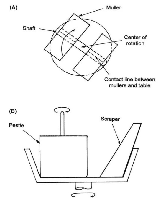
FIGURE 12.3 (A) Edge runner mill and (B) end
runner mill.
Hammer Mill
The
hammer mill typifies a group of machines operating at very high speeds and
acting primarily by impact on a freely suspended particle. The term
“dis-integrator” is also used. High efficiency, which would be expected from
the operation of a free-crushing mechanism, is reduced because the blows
delivered are in excess of the minimum required for breakage.
A
typical machine is shown in Figure 12.4A. It consists of a disk rotating at
speeds up to 8000 rpm. The higher speeds are used for fine grinding in
relatively small machines. A balanced number of hammers are fitted to the disk.
These may be fixed or pivoted, presenting flat, knife, or file edges to the
material. The material is fed to the top or the center of the mill and is
broken by direct impact until it is fine enough to pass through the screen,
which forms the lower part of
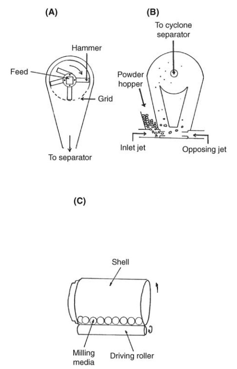
FIGURE 12.4 (A) Impact mill with pivoted
hammers, (B) comminution mill, and (C) ball mill.
A range of screens are normally provided. Because of tangential
exit, the product size is considerably smaller than the screen apertures. The
disk and hammers act as a centrifugal fan, drawing large volumes of air through
the mill. Entrained dust must be separated with a bag filter or a cyclone
separator.
The
mill will process dry, crystalline materials, which do not soften under milling
conditions, and many crude drugs. The speed of rotation and the size and shape
of the screen apertures are interrelated factors controlling the size of the
product. A considerable amount of very fine powder is produced. A marked rise
in temperature can occur during passage through the mill, with consequent risk
of fusion or decomposition of susceptible drugs.
Great
versatility, derived from simple variation of screen, rotor speed, and type of
blade, is characteristic of the refined mills commonly used in the
pharmaceutical industry. The “Fitzmill” (The Fitzpatrick Company of America and
Manesty Machines Limited) and the “Apex” comminuting mill (Apex Construction
Company, London) are mobile machines constructed largely of stainless steel.
The general principle is illustrated in Figure 12.4B. Both offer a large screen
area and operate at various speeds. A reversible rotor permits the use of
blades presenting either a flat, impact face or a cutting edge to the material.
Materials are ground by high-speed operation of the impact face. The knife
edges may be used at lower speeds for wet granulation and the precision
reduction of the imperfect tablets produced during dry granulation. The mill
may be jacketed to control milling temperatures. Mixing, wet grinding, and
ointment milling may also be performed.
Pin Mill
Pin
mills consist of two horizontal steel plates with vertical projections arranged
in concentric circles on opposing faces and becoming more closely spaced toward
the periphery. The projections of the two faces intermesh. The material is fed
through the center of the stationary upper disk onto the lower revolving disk
and is propelled by centrifugal action toward the periphery. The passage
between the pins provides size reduction by impact and attrition. The material
is collected in the annular space surrounding the disks and passes to a
separator. The large volumes of air drawn through the mill are discharged
through the separator. Absence of screens and gratings provides an action that
is free from clogging. The machine is suitable for grinding soft, nonabrasive
powders, and low milling temperatures permit the processing of heat-sensitive
materials. The fineness of the grind may be varied by the use of disks with
different dis-positions of pins.
Ball Mill
The
ball mill is widely used for fine grinding. Extremely fine powders may be
produced, although milling times are often protracted. Despite simple
con-struction, the mill is extremely versatile. It can be used for wet or dry
grinding in continuous or batch processes. The latter are usually imposed by
the scale of pharmaceutical operations. The mill is closed. Sterility can
therefore be main-tained or an operation can be conducted in an inert
atmosphere if the process demands such conditions. Materials of widely
differing mechanical properties can be ground by the combined effects of impact
and attrition characteristic of the mill.
The
ball mill, in its simplest form, is illustrated in Figure 12.4C. It consists of
a rotating, hollow cylinder containing balls usually made of stainless steel or
stoneware. During grinding, the balls slowly wear and are eventually replaced.
For general purposes, the mill will therefore contain balls of different sizes,
which perform different functions. The loading of the mill varies. Typically,
the mill is half filled with balls and the material to be ground is added to
overfill the interstices between the balls. The apparent volume of the total
charge is com-monly 60% of the mill volume. In operation, the distance the
charge moves up the mill casing depends on the centrifugal force. This is a
function of the speed at which the mill rotates and the friction between charge
and mill lining. These effects determine the pattern of movement within the
mill. At low grinding speeds, the balls tumble, roll, and jump down the free
face of the charge, a pattern described as “cascading.” With increase in speed,
the pattern progres-sively changes to “cataracting” in which the balls are carried
almost to the top of the mill and fall directly onto the charge below.
The
grinding contributions of impact and attrition vary in these patterns of
movement. Attrition predominates in the cascading mill and depends, to some
extent, on the surface area of the balls. The effect can therefore be enhanced
by the use of small balls. Impact breaking becomes more important in the
cata-racting mill, the most effective action being derived from the high
kinetic energy of the larger balls, a factor also influenced by the latter’s
density.
If
there is sufficient friction between the mill lining and the charge, the latter
will “key” to the mill at higher speeds and rotate with it. This is termed
“centrifuging,” and since there is no relative movement between the balls, no
grinding occurs. The speed marking the onset of centrifuging is called the
critical speed. Theoretically, it represents conditions for which the
centrifugal and gravitational forces acting on a ball at the top of the mill
are balanced. If the mass of the ball is m, the gravitational force is given by
mg and the centrifugal force is mvc2/r,
where vc is the critical speed and r is the distance of the ball
from the axis of the mill, that is, the radius of the mill minus the radius of
the ball. These may be equated to give
vc = √(gr) (12:4)
In
practice, centrifuging does not occur until well above the theoretical critical
speed, and it varies with mill loading and the amount of slip between charge
and lining. Mills usually operate at between 50% and 80% of the critical speed.
The lower speeds are used for wet grinding and very fine dry grinding.
If
a low coefficient of friction permits extensive slipping between mill and
charge, centrifuging will not occur even at very high mill speeds. Under these
“supercritical” conditions, the grinding action differs from the pattern
described above.
By
correct choice of ball size, mill speed, and diameter, the ball mill may be
used to grind material of widely different particle size. In coarse dry grinding,
the energy is associated with the largest ball falling and the diameter of the
mill must be sufficient to break the largest particle. Very fine grinding, on
the other hand, is best effected by the attrition between a large number of
small balls. The most important limiting factor in the production of very fine
particles by milling is agglomeration. Ultimately, the reduction of new surface
by rebonding may equal the increase in surface due to fracture. This is shown
as point A in the relation of specific surface area and milling time given in
Figure 12.5. With further grinding, the effective particle size may actually
increase. Agglomeration during fine dry grinding is usually more severe than
that in wet grinding. In both cases, however, additives can sometimes be used
to limit its effect.
The
ball mill also provides a simple mechanical means of producing dis-persions of
solids in liquids. Wet grinding depends on the attrition characteristic of the
cascading mill. The smaller the balls, the greater the effect and the greater
the viscosity of the suspension. The latter should not prevent the correct
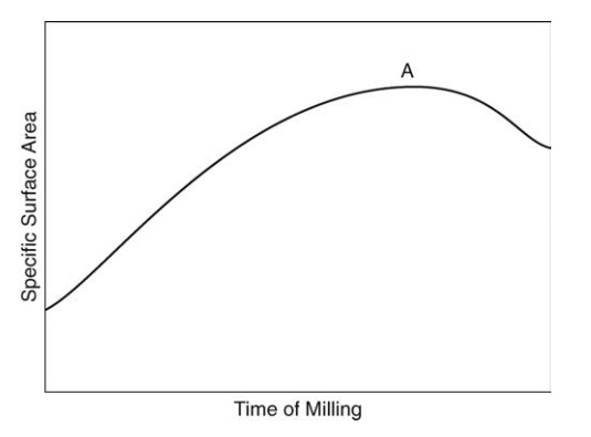
FIGURE 12.5 The effect of particle agglomeration during milling.
Where their use is permissible, the addition of surface-active
agents may greatly accelerate the process by preventing reaggregation of the
particles. Surface-active agents can also alter the physical properties of the
solid, lowering the breaking strain and rendering the particle more brittle. A higher
ratio of solids to liquid, which aids efficient milling, is possible if the
system is deflocculated.
In
large-scale, continuous installations, the mill may be modified to apply
grinding forces appropriate to the size of particle being ground. In the tube
mill, the ratio of length to diameter is greatly increased and the mill is
divided into several compartments, each containing balls of different average
size. The coarse material first enters the compartment containing the largest
balls. It is then conveyed to successive compartments containing smaller balls
and capable of progressively finer grinding. In the Hardinge conical ball mill,
natural segre-gation is induced by the conical shape. The largest balls operate
at the largest diameter and, through the kinetic energy acquired during the
extensive fall, create high-impact stresses suitable for breaking coarse
particles. The material first passes through this region. With further progress
through the mill, the greater surface presented by the smaller balls promotes
finer grinding by attrition.
Vibratory Mill
In
the ball mill, the energy for grinding is derived from the acceleration of the
balls in a gravitational field. Under normal conditions, the latter limits the
speed at which a mill of a given diameter can be run and therefore limits the
rate at which energy can be applied to the process. Long milling times are
characteristic of the ball mill. The advantage of vibratory milling is centered
mainly on this limitation since it is possible, by this method, to develop
accelerations much greater than those induced by the earth’s gravitational
field. Grinding can be more energetic, and milling times can be greatly
reduced.
A
simple form of vibratory mill consists of a mill body containing the grinding
media, usually of porcelain or stainless steel balls. The mill body is
supported on springs, which permit an oscillatory movement. This vibration is
usually, but not necessarily, in a vertical plane. The suspended mass is
main-tained in a state of forced vibration by some means such as the rotation
of a shaft on which unbalanced weights are mounted. The charge is subjected to
move-ments of high frequency and small amplitude. The resultant chattering of
the mill gives comminution by attrition. Characterized by relatively high-speed
grinding, the mill is usually more flexible than the ball mill, charging and
dis-charging and adaption to continuous processing being much easier. The more
efficient use of the energy applied and the shorter grinding times usually result
in lower milling temperatures than that found in a ball mill. Construction,
however, is more complex, and the feed size of the material is limited to
approximately 0.25 in. or less. The mill is not suitable for grinding resilient
materials, which cannot be ground by impact since the shear forces developed
are less than those found in a ball mill.
A
refined example of this principle is found in the Podmore-Boulton vibro-energy
mill, shown in Figure 12.6A. This consists of an annular grinding chamber generally
accommodating a medium of small cylinders. These align coaxially in a
three-dimensional vibratory field to give close packing and line
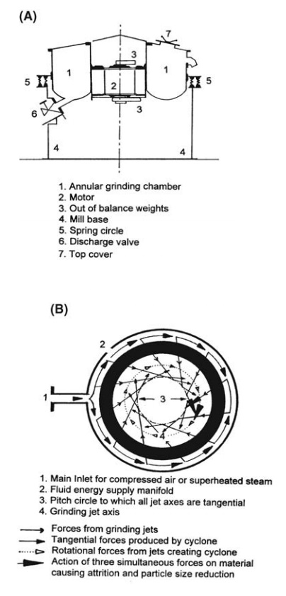
FIGURE 12.6 Diagrams of (A) vibro-energy mill and (B) fluid energy mill.
This, it is claimed, gives preferential grinding of
coarse material, leading to products with narrow particle size distributions.
Fluid Energy Mill
The
fluid energy mill offers an alternative method of producing very fine powders.
The term “micronizer” is in general use and is a trade name coined by a company
that originated a particular type of fluid energy mill. In all fluid energy
mills, the grinding results mainly from attrition between the particles being
ground, the energy inducing movement of the particles being supplied in the
form of compressed fluids. Air and steam are widely used.
A
common type of fluid energy mill is illustrated in Figure 12.6B. The material
is blown into the grinding chamber through a venturi feed placed at its
perimeter. The compressed fluid enters the chamber through nozzles tangential
to a hypothetical circle within the grinding chamber. The particles are
violently accelerated by the rotating fluids and are subjected to the influence
of successive nozzles. Grinding results from impact between particles, which
are then sub-jected to the intense classifying action of the circulating fluid.
Oversize particles remain in the grinding zone, while fine powder and spent
grinding fluid spiral to the central outlet.
For
a given machine, the size reduction depends on the size of the feed, its rate
of introduction to the grinding chamber, and the pressure of the grinding
fluid. The most important machine factors are the geometry of the grinding
chamber and the number and angle of the nozzles.
Powders
with all particles below a few microns may be quickly produced by this method.
The disadvantage of high capital and running costs may not be so serious in the
pharmaceutical industry because of the high value of the materials that are
often processed. For grinding drugs, the mill is usually made of stainless steel. Large volumes of air compressed
to about 6.89 x 10⁵ N/m2 must be provided.
Colloid Mills
Colloid
mills are a group of machines used for wet grinding and dispersion. They
operate by shearing relatively thin layers of material between two surfaces,
one of which is moving at a high angular velocity relative to the other.
Although very fine dispersions can be produced, they are not, as the name
implies, of colloidal dimensions. Colloid mills are also widely used in the
preparation of emulsions.
A
typical colloid mill consists of a stator and a rotor with flat working
surfaces. These are often made of stainless steel or carborundum. The clearance
is adjustable from virtually zero upward. The rotor is rotated at several
thou-sand revolutions per minute, and the slurry of already fine material
passes through the clearance under the action of centrifugal forces.
Surface-active agents fulfill the same function in colloid mills as in ball
milling.
Roller Mills
Roller
mills may be used to grind pastes and other plastic dispersions. They operate
by inducing crushing and shearing forces in a thin layer of the paste as it
passes through the narrow clearance between two rollers. Commonly, shear forces
are intensified by the differing peripheral velocity of the rolls. The
clearance between the rolls is variable and depends on the plasticity of the
mass, the gap increasing as the stiffness of the material increases. With thin
pastes, the milling action is similar to the colloid mill.
Related Topics