Evaporators
| Home | | Pharmaceutical Technology |Chapter: Pharmaceutical Engineering: Evaporation and Distillation
It is convenient to classify evaporators into the following: natural circulation evaporators, forced circulation evaporators, and film evaporators.
EVAPORATORS
It
is convenient to classify evaporators into the following: natural circulation
evaporators, forced circulation evaporators, and film evaporators.
Natural Circulation Evaporators
Forced Circulation Evaporators
Film Evaporators
The Efficiency of Evaporators
Vapor Removal and Liquid Entrainment
Evaporation without Boiling
Natural Circulation Evaporators
Small-scale
evaporators consist of a simple pan heated by jacket, coil, or by both.
Admission of the heating fluid to the jacket induces a pool boiling regime in
the
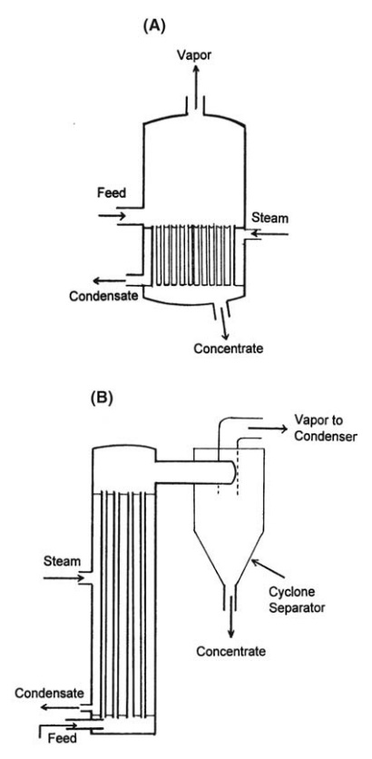
FIGURE 10.3 (A) Evaporator with calandria and (B) climbing film evaporator.
Very small evaporators may be open, the vapor escaping to the atmo-sphere or
into a vented hood. Larger pan evaporators are closed, the vapor being led away
by pipe. Small jacketed pans are efficient and easy to clean and may be fitted
for the vacuum evaporation of thermolabile materials. However, because the
ratio of heating area to volume decreases as the capacity increases, their size
is limited, and larger vessels must employ a heating coil. This improves
evaporating capacity but makes cleaning more difficult.
The
large heating area of a tube bundle is utilized widely in large-scale
evaporators. Horizontal mounting, with the heating fluid inside the tube, is
limited by poor circulation to the evaporation of nonviscous liquids in which
the bundle is immersed. Normally, the tube bundle is mounted vertically and is
known as a calandria. The boiling of liquids in a vertical tube and the earlier
regimes of this process operate in a calandria. The length of tubes and the
liquid level are such that boiling occurs in the tubes and the mixture of vapor
and liquid rises until the entire calandria is just submerged. A typical
evaporator is shown in Figure 10.3A. The tubes are from 1.2 to 1.8 m in length
and 5.1 to 7.6 cm in diameter. The low density of the boiling liquid and vapor
creates an upward movement in the tubes. Vapor and liquid separate in the space
above the calandria, and the liquid is returned to the pool at the base of the
tubes by a large central downcomer or through an annular space between the
heating element and the evaporator shell. Feed is added and concentrate is
withdrawn from the pool, as shown in the figure. As long as the viscosity of
the liquid is low, good circulation and high heat transfer coefficients are
obtained.
In
some evaporators, the calandria is inclined and the tubes are lengthened.
Forced Circulation Evaporators
On
the smallest scale, forced circulation evaporators are similar to the pan
evaporators described above, modified only by the inclusion of an agitator.
Vigorous
agitation increases the boiling film coefficient, the degree depending on the
type and speed of the agitator. An agitator should be used for the evaporation
of viscous materials to prevent degradation of material at the heated surfaces.
Some
large-scale continuous units are similar to the natural circulation evaporators
already described. The natural circulation induced by boiling in a vertical
tube may be supplemented by an axial impeller mounted in the downcomer of the
calandria. This modification is used when viscous liquids or liquids containing
suspended solids are evaporated. Such units are employed in evaporative
crystallization. In other forced circulation evaporators, the tube bundle
becomes, in effect, a simple heat exchanger through the tubes of which the
liquid is pumped. Commonly, the opposing head suppresses boiling in the tubes.
Superheating occurs, and the liquid flashes into a mixture of liquid and vapor
as it enters the body of the evaporator.
Film Evaporators
In
the short tubes of the calandria, an intimate mixture of vapor and liquid is
discharged at the top. If the length of the tube is greatly increased,
progressive phase separation occurs until a high-velocity core of vapor is
formed, which propels an annular film of liquid along the tube. This phenomenon,
which is a stage of flow when a liquid and a gas pass in the same direction
along a tube, is employed in film evaporators. The turbulence of the film gives
very high heat transfer coefficients, and the bubbles and vapor evolved are
rapidly swept into the vapor stream. Although recirculation may be adopted, it
is possible, with the high evaporation rates found in long tubes, to
concentrate the liquid sufficiently in a single pass. Since a very short
residence time is obtained, very thermolabile materials may be concentrated at
relatively high temperatures. Film evaporators are also suitable for materials
that foam badly. Various types have been developed, but all are essentially
continuous in operation, their capacity ranging from a few gallons per hour upward.
The
climbing film evaporator, which is the most common film evaporator, consists of
tubes 4.6 to 9.1 m in length and 2.5 to 5.1 cm in diameter mounted in a steam
chest. This arrangement is described in Figure 10.3B. The feed liquid enters
the bottom of the tubes and flows upward for a short distance before boiling
begins. The length of this section, which is characterized by low heat transfer
coefficients, may be minimized by preheating the feed to its boiling point. The
pattern of boiling and phase separation follows, and a mixture of liquid and
vapor emerges from the top of the tube to be separated by baffles or by a
cyclone separator. Climbing film evaporators are not suitable for the
evaporation of viscous liquids.
In
the falling film evaporator, the liquid is fed to the top of a number of long
heated tubes. Since gravity assists flow down the tube, this arrangement is
better suited to the evaporation of moderately viscous liquids. The vapor
evolved is usually carried downward, and the mixture of liquid and vapor
emerges from the bottom for separation. Even distribution of liquid must be
secured during feeding. A tendency to channel in some tubes will lead to drying
in others.
The
rising-falling film evaporator concentrates a liquid in a climbing film section
and then leads the emerging liquid and vapor into a second tube section, which
forms a falling film evaporator. Good distribution in the falling film section
is claimed, and the evaporator is particularly suitable for liquids that
increase greatly in viscosity during evaporation.
In
mechanically aided film evaporators, a thin film of material is main-tained on
the heat transfer surface irrespective of the viscosity. This is usually
achieved by means of a rotor, concentric with the tube, which carries blades
that either scrape the tube or ride with low clearance in the film. Mechanical
agita-tion permits the evaporation of materials that are highly viscous or that
have a low thermal conductivity. Since temperature variations in the film are
reduced and residence times are shortened, the vacuum evaporation of viscous
ther-molabile materials becomes possible.
The Efficiency of Evaporators
In
the pharmaceutical industry, economic use of steam may not be of overriding
importance because the small scale of the operation and the high value of the
product will not justify the additional capital costs of improved heating
effi-ciency. In other industries, heating costs impose more efficient use of
heat. This is secured by utilizing the heat content of the vapor emerging from
the evapo-rator, assumed, until now, to be lost in a following condensation.
Two methods commonly used are multiple effect evaporation and vapor
recompression.
In
multiple effect evaporation, the vapor from one evaporator is led as the heating
medium to the calandria of a second evaporator, which, therefore, must operate
at a lower temperature than the first. This principle can be extended to a
number of evaporators, some stages working under vacuum. The limit is set by
the relation of the cost of the plant and the vacuum services with the cost of
the steam that is saved.
In
evaporators employing vapor recompression, the vapor emerging is compressed by
mechanical pumps or steam jet ejectors to increase its temper-ature. The
compressed vapor is returned to the steam chest.
Vapor Removal and Liquid Entrainment
Vapor
must be removed from the evaporator with as little entrained liquid as
possible. The two determining factors are the vapor velocity at the surface of
the liquid and the velocity of the vapor leaving the evaporator. On a small
scale, surface vapor velocities will be low, but with increase in scale, the
adverse ratio of surface area to volume creates higher velocities. Droplets
formed by the bursting of bubbles at the boiling surface may then be projected
from the surface. In addition, foam may form. Various devices may be used to
control entrainment at or near the surface. A high vapor space is provided
above the boiling liquid to allow large droplets to fall and foam to collapse.
Baffles may be used in the vapor space to arrest entrained droplets. Where
allowable, antifoaming agents, such as silicone oils, can be used to depress
foaming.
Stokes’
law shows that vapor of particular characteristics will carry droplets upward
against the force of gravity. Any entrained liquid not inter-cepted in the body
of the evaporator will, therefore, be carried forward in the higher-velocity
stream of the vapor uptake. Some droplets will be caught here, the quantity
depending on the geometry of the duct and the velocity of the vapor. At
atmospheric pressure, the latter might be 17 m/sec. In vacuum evaporation, much
higher velocities may be used. When the quantity of entrained liquid is high,
the vapor is commonly led to a cyclone separator. This is employed with
frothing materials and the vapor-liquid mixture leaving a climbing film
evaporator. In the separator, the entrained liquid is flung out to the walls by
centrifugal force and may be collected or returned to the evapo-rator. The
vapor is led to a condenser.
Evaporation without Boiling
During
heating, some evaporation takes place at the surface of a batch of liquid
before boiling begins. Similarly, liquids that are very viscous or that froth
excessively may be concentrated without boiling. The diffusion of vapor from
the surface is then described by equation (4.5) as:
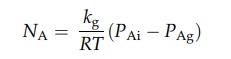
where
NA is the number of moles evaporating from unit area in unit time,
kg is the mass transfer coefficient across the boundary layer, R is the gas
constant, T is the absolute temperature, PAi is the vapor pressure
of the liquid, and PAg is the partiale pressure of the vapor in the
gas stream. kg is proportional to the gas velocity.
Related Topics