Pumps
| Home | | Pharmaceutical Technology |Chapter: Pharmaceutical Engineering: Fluid Flow
Pumps can be divided into positive displacement pumps, which may be reciprocating or rotary, and impeller pumps.
PUMPS
Equations
(2.8) and (2.9) examined the power requirement for driving a liquid through a
system against an opposing head. This energy is normally added by a pump. In
different processes, the quantities to be delivered, the opposing head, and the
nature of the fluid vary widely, and many pumps are made to meet these
differing requirements. Basically, however, pumps can be divided into positive
displacement pumps, which may be reciprocating or rotary, and impeller pumps.
Positive displacement pumps displace a fixed volume of fluid with each stroke
or revolution. Impeller pumps, on the other hand, impart high kinetic energy to
the fluid, which is subsequently converted to pressure energy. The volume
discharged depends on the opposing head.
Equipment
for pumping gases and liquids is essentially similar. Machines delivering gases
are commonly called compressors or blowers. Compressors discharge at relatively
high pressures, and blowers, at relatively low pressures. The lower density and
viscosity of gases lead to the use of higher operating speeds and, to minimize
leakage, smaller clearance between moving parts.
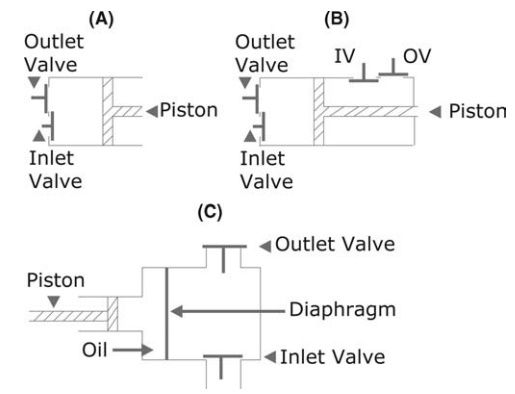
FIGURE 2.13 Positive displacement pumps (A) Reciprocating Piston; (B) Double Acting
Piston and (C) Diaphragm pumps.
Positive Displacement Pumps
Positive
displacement pumps are most commonly used for the discharge of relatively small
quantities of fluid against relatively large heads. The small clearance between
moving parts precludes the pumping of abrasive slurries.
The single-acting
piston pump in Figure 2.13A exemplifies the recip-rocating pump. The fluid is
drawn into a cylinder through an inlet valve by movement of the piston to the
right. The stroke in the opposite direction drives fluid through the outlet
valve. Leakage past the piston may be prevented by rings or packing. Cessation
of pumping on the return stroke is overcome in the double-acting piston pump by
utilizing the volume on both sides of the piston. Fluid is drawn in on one side
by a stroke that delivers the fluid on the other (Fig. 2.13B). In both pumps,
delivery fluctuates. Operation, however, is simple, and both are efficient
under widely varying conditions. The principle is widely used in gas
compressors. In pumping liquids, no priming is necessary because the pump will
effectively discharge air present in the pump or feed lines.
A modification,
known as the diaphragm pump, is constructed so that reciprocating parts do not
contact the pumped liquid (Fig. 2.13C). A flexible disk, fixed at the
periphery, expands and contracts the pumping chamber, drawing in and
discharging liquid through valves.
Rotary
positive displacement pumps operate, presenting an expanding chamber to the
fluid that is then sealed and conveyed to the outlet. Both liquids and gases
are discharged so that priming is not necessary. The principle is illustrated
in Figure 2.14, which describes a gear pump, a lobe pump, and a vane pump. In
the gear pump, the liquid is conveyed in the spaces formed between a case and
the consecutive teeth of two gears that intermesh at the center of the pump to
prevent the return of the liquid to the inlet. The lobe pump, widely used as a
liquid pump and as a blower, operates in a similar manner. Each impeller
carries two or three lobes that interact with very small clearance to convey
fluid from inlet to outlet.
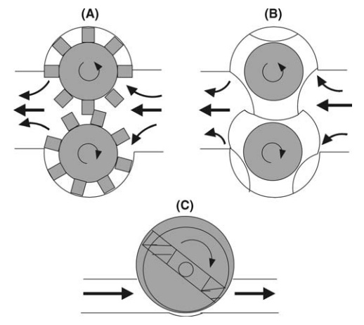
FIGURE 2.14 Rotary Pumps: (A) Gear; (B)
Lobe; and (C) Vane.
Sliding
vanes, mounted in the surface of an off-center rotor but maintained in contact
with the case by centrifugal force or spring loading, provide the pumping
action of the vane pump. Fluid is drawn into the chamber created by two vanes
at the inlet. The fluid is rotated and expelled by contraction at the outlet.
Besides liquid pumping, the principle of the vane pump is used in blowers and,
by evacuating at the inlet and discharging to atmosphere at the outlet, in
vacuum pumps.
The
Mono pump consists of a stator in the form of a double internal helix and a
single helical rotor. The latter maintains a constant seal across the stator,
and this seal travels continuously through the pump. The pump is suitable for
viscous and nonviscous liquids. The stator is commonly made of a rubber or
similar material, so slurries are effectively delivered. Discharge is
nonpulsating and can be made against very high pressures. The pump is commonly
used to drive clarifying and cake filters.
Centrifugal Impeller Pumps
The
centrifugal impeller pump is the type most widely used in the chemical
industry. The impeller consists of a number of vanes, usually curved backward
from the direction of rotation. The vanes may be open or, more commonly, closed
between one or two supporting plates. This reduces swirl and increases
efficiency. The impeller is rotated at high speeds, imparting radial and
tangential momenta to a liquid that is fed axially to the center and that
spirals through the impeller. In the simple volute pump (Fig. 2.15A), the
liquid is received into a volute chamber. The cross section increases toward
the tangential outlet. The liquid, therefore, decelerates, allowing a
conversion of kinetic energy to pressure energy. In
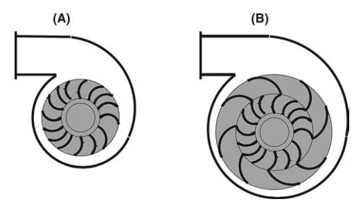
FIGURE 2.15 Centrifugal Impeller Pumps: (A)
Volute and (B) Diffuser.
the diffuser pump,
correctly aligned blades of a diffusing ring over which the fluid velocity
decreases smoothly receive the liquid from the impeller, and the pressure
rises. Flow through a diffuser pump is described in Figure 2.15B.
Because of the less
precise control of the direction of the liquid leaving the impeller, the volute
pump is less efficient than the diffuser pump. However, it is more easily
fabricated in corrosion-resistant materials and is more commonly used. The
pump, which is compact and without valves, may be used to pump slurries and
corrosive liquid, steadily delivering large volumes against moder-ately large
heads. For large heads, pumps are used in series. Unlike positive displacement
pumps, impeller pumps continue to operate if the delivery line is closed, the
kinetic energy of the liquid being degraded to heat.
A
disadvantage of the centrifugal pump is that the conditions under which a pump
of given size will operate with high efficiency are limited. The relation
between the quantity discharged and the opposing head for a volute pump
operating at a given speed is shown in Figure 2.16. As the head increases, the
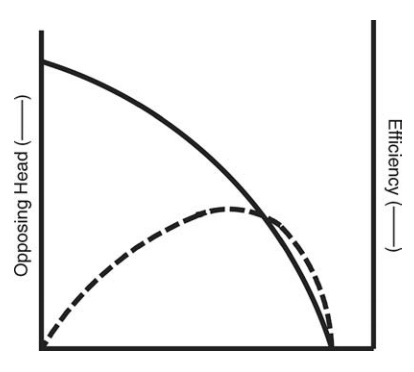
FIGURE 2.16 Performance curve of a volute pump running at fixed speed.
quantity
discharged decreases. The mechanical efficiency of the pump is the ratio of the
power acquired by the liquid, given by equation (2.9), to the power input. A
maximum value is shown in Figure 2.16, indicating optimal operating conditions.
The effect on the efficiency when the pump operates at other con-ditions can be
seen from the figure, and to achieve reasonable operating effi-ciency for a
given discharge and opposing head, a pump of suitable size and operating speed
must be used.
A
second disadvantage of the centrifugal pump lies in priming. If the pump
contains air alone, the low kinetic energy imparted by the impeller creates a
very small pressure increase across the pump, and liquid is neither drawn into
the pump nor discharged. To begin pumping, the impeller must be primed with the
liquid to be pumped. Where possible, the pump is placed below the level of the
supply. Alternatively, a nonreturn valve could be placed on the suction side of
the pump to prevent draining when rotation ceases.
The
same principle is employed in centrifugal fans and blowers used to displace
large quantities of air and other gases. The gas enters the impeller axially
and is moved outward into a scroll. The opposing static head is usually small,
and energy appears mainly as the kinetic energy of the moving gas stream.
Other Impeller Pumps
The
propeller pump, exemplified by a domestic fan, is used to deliver large
quantities of fluids against low heads. These conditions are common in
recir-culation systems. The principle is also employed in fans used for
ventilation, the supply of air for drying, and other similar operations.
Example 1
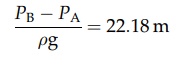
In
the figure, what is the energy loss due to pressure?
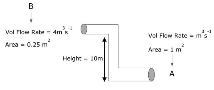
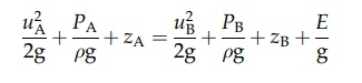
Using
Bernoulli’s equation, we obtain
Calculate
the velocity head and potential head at points A and B.
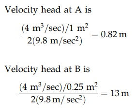
Potential
head at A = 0 m
Potential
head at B = 10 m
Friction
head = 0 m
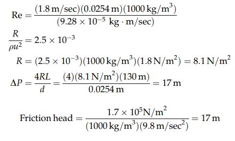
Example 2
Calculation
of pressure drop in a pipe due to friction.
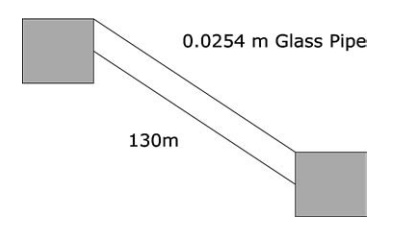
For
a smooth 0.08-m pipe, 130-m long, find the friction head. The density of water
is 1000 kg/m3 and the viscosity of water is 9.28 x 10⁻⁵
kg·m/sec.
Calculate
the Reynolds number.
Related Topics